Universal Serial Parser (USP) Guide
There are many machines and sensors which can emit streams of data over a serial interface and also receive control commands over the same interface.
Octave includes a Universal Serial Parser (USP) service that accepts such data from a serial interface on an Octave edge device, and makes it available as Resources. The data can then be interpreted in an Edge Action script to extract valuable information. The service also provides the capability to send commands via this same serial interface.
The service is exposed as any other Octave Service (e.g., Modbus, CANopen , GPIO, etc.). The service receives a configuration from the cloud and exposes Resources to read and write data from the serial link.
Supported versions
For edge firmware release 3.1 and above:
- "String" mode is supported
- The USP service can be configured easily thanks to the dedicated USP user interface
For 3.2 and above: USP on both UARTs at the same time is supported.
You can work with USP ins two ways:
- Configuring USP via the USP Screen: this is available for devices with FW release 3.1 or greater. Set the configuration (/usp/config) graphically using Octave's USP Service screen. Once configured, you can then communicate over USP by working directly with the /value and /write USP Resources.
- Configuring the USP Resources Directly: work directly with all three of the aforementioned Resources to configure and communicate using USP.
Message Framing Strategies
Before continuing, it's important to understand the three strategies available to adapt to the way messages are framed on the serial link using USP:
- Fixed length: the service reads a fixed number of bytes from the serial link as defined in the configuration, and stores the data in a buffer. Once that number of bytes have been read, the service writes the content of the buffer to /value.
- Delimiter: the service looks for one of the matching delimiters defined in the configuration, matching on the shortest delimiter first. This strategy is therefore useful for variable-length payloads. A delimiter is the decimal representation of 1 to 4 bytes, and up to 255 delimiters can be defined. All the data read on the serial link is accumulated in a buffer, and when the delimiter is found, the service writes the content of the buffer to the variable: /value. The delimiter is included in the data reported. This strategy is convenient for text-based protocols where protocol data units (PDUs) are delimited by carriage return, or NFC reader messages terminating by 0x03. The following rules are in place based on the string mode:
- If string mode is set to false, the delimiter method allows a maximum of 512 delimiters of 4 bytes (max) to be set at one time.
- If string mode is set to true, only the first delimiter is taken into account with a maximum of 4 bytes.
- Dynamic length: this configuration is used to match protocols providing the length of the frame at a fixed position. The configuration must indicate:
- the position of the length field in the frame (start)
- the size of the length field (size)
- the encoding of the length field (big endian (set to true for big endian or false for little endian))
- the offset (offset), which is a value to be added to the read length field, in order to add trailing bytes (e.g., CRC bytes).
Once the number "length field value" + "offset" is reached, the service writes the content of the buffer to the variable /value.
Configuring USP via the Service Page
This screen is available for devices with edge firmware 3.1 or above. Devices with a lower firmware version should use the manual configuration procedure indicated further below.
Octave's USP configuration screen provides a convenient graphical UI to configure USP (i.e., to configure /usp/config without having to work directly with JSON).
Follow the steps below to access the USP configuration screen:
- Ensure you have a device selected in the Octave Dashboard.
- Navigate to Device > Services and locate the Universal Serial Parser section.
- Select a UART on which to set up USP communications. Note that one of the UARTs will be disabled if it has already been allocated to another Service (e.g., GPIO). The USP configuration screen is then displayed with UART settings at the top (1) and USP-specific settings at the bottom (2):
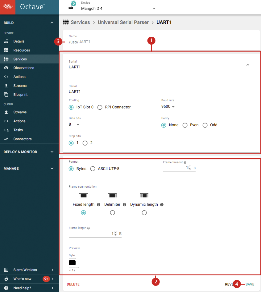
- (Optional) Enter a unique name into the UART's Name field (3) and configure the UART settings on the screen as required for communication with the asset over UART.
- Configure the USP format and click Save (4). The format settings are described below.
General USP Settings
The following general settings can be applied:
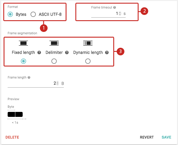
- Format (1): specifies if data frames consist of raw 8-bit bytes or ASCII UTF-8 bytes. If ASCII mode is selected, the delimiters are removed by Octave so that only the characters of interest (i.e., the characters in the payload) are retained and displayed in Octave.
- Frame timeout (2): the maximum duration, in seconds, for the system to read a frame.
- Frame segmentation (3): sets the Message framing strategy. The fields for each strategy are described in more detail below.
Fixed Length Configuration
Fixed length provides the following configuration settings to define fixed-length frames of data:
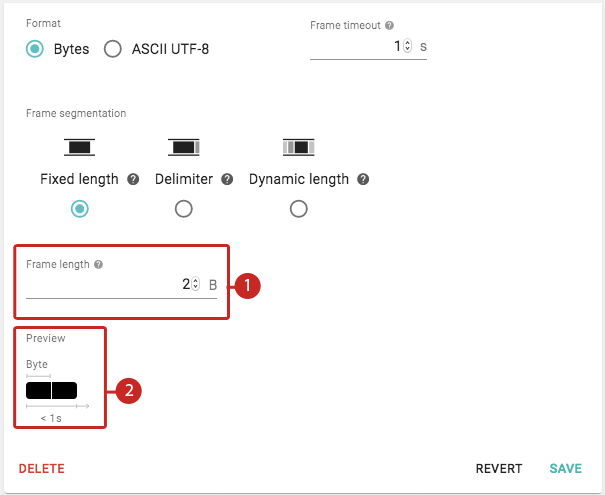
- Frame length (1): specifies the number of bytes that make up a payload for a frame of data.
- Preview (2): shows a graphical preview of the number of bytes that the system will consider as a frame of data when received within the specified frame timeout.
Delimiter Configuration
Delimiter provides the following configuration settings to define frames of data consisting of a variable number of bytes for the payload and a delimiter to mark the end of a frame:
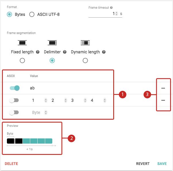
- Delimiter Configuration (1): specifies one or more delimiters. Each delimiter can be defined as up to four bytes of either raw decimal values or ASCII characters. Enabling ASCII displays the byte(s) as ASCII characters. This can be useful for example, when the bytes comprise a human-readable word such as OK or ERR.
- Preview (2): shows a graphical preview of the number of payload and delimiter bytes that the system will consider as a frame of data when received within the specified frame timeout. The number of delimiter bytes shown is based on the longest sequence of delimiter bytes configured, however, Octave will try to match all configured sequences of delimiter bytes.
- Delete (3): click the bar to remove a delimiter.
Dynamic Length Configuration
Dynamic length (applicable only to the Bytes format) provides the following configuration settings to send variable-length frames of payload data:
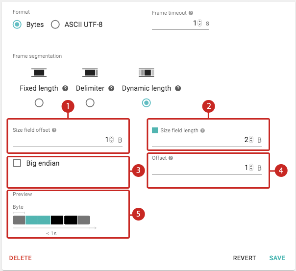
- Size field offset (1): specifies the number of bytes from the start of the frame at which the size field is located within the frame. The size field is the bytes which specify the length of the frame of data.
- Size field length (2): the number of bytes which comprise the size field.
- Big endian (3): specifies if the bytes which define the size are in little endian (default) or big endian format.
- Offset (4): specifies the number of trailing bytes to add to the end of the frame of data.
- Preview (5): shows a graphical preview of the number of payload, size, and offset bytes that the system will consider as a frame of data when received within the specified frame timeout.
Configuring the USP Resources Directly
The following sub sections show to how work directly with the USP-related Resources to configure and communicate using USP.
Configuring the /usp/config Resource Directly
The USP service is configured by modifying the JSON content in the /usp/config Resource:
{
  "uart": "UART0" | ... | "UARTn",   // String, Mandatory
  "frame_timeout": 0.5,              // Timeout in seconds. Must be set to a value greater than 0. After waiting this amount of time without completing a message, reset the accumulation state and the parser state machine
  "string" : true | false,           // Optional. Default value if false. If true, data format is an ASCII string (UTF-8), else format is byte array.
  "name" : "<name>",                 // Optional. USP resource path.

  // Framing of serial data: choose one of the 3 strategies:
  "framing": {
     "fixed": 34,// Accumulate the number of specified bytes
    // or
     "delimiter":[[13, 10], [32]],       // Accumulate bytes (in decimal) on the serial port until matching one of the specified separators
    // or
      "lenfield" : {"start":2, "size":2, "bigendian":true, "offset":0}, // Accumulate bytes based on a length field which define the number of byte to accumulate
  }
}
The framing values fixed, delimiter, and lenField correspond to the Fixed length, Delimiter, and Dynamic length Message Framing Strategies respectively and are configured as follows:
- fixed: a numeric value specifies the number of bytes to read from the serial link.
- delimiter: an array of delimiters (decimal representation of 1 to 4 bytes) on which to match.
- lenField: an object defining the configuration with the following fields:
- the position of the length field in the frame (start).
- the size of the length field (size).
- the encoding of the length field (big endian (set to true for big endian or false for little endian)).
- the offset (offset), which is a value to be added to the read length field, in order to add trailing bytes (e.g., CRC bytes).
In addition, a UART must be assigned to the USP service in the /io/config Resource. This is done by setting the USP service to "own" the UART via the "own":"usp" field:
{
   "devs":[
      {
         "conf":[
            {
               "baud":"38400",
               "bits":"8",
               "flow":"N",
               "own":"usp",
               "pair":"N",
               "std":"232",
               "stop":"1",
               "type":"UART1",
               "wire":"2"
            }
         ],
         "type":"serial"
      }
   ]
}
USP Resource Paths
In firmware versions below 3.2.0, USP Resources are accessed via the following fixed paths:
- /usp/config: configuration of the USP Resource in JSON format (described in the previous section).
- /usp/value: decoded message following the configuration.
- /usp/write: message to send over the serial bus. This can be a JSON array of unsigned bytes:
[123,23,255,0]or a string of ASCII representation of the dataAT+AI8.
With support for multiple USP links in firmware 3.2.0 and above, you can specify a unique name by adding the (optional) name field for the USP link via the /usp/config JSON. The value and write paths are specified according to the following rules:
| Configuration | Paths |
|---|---|
One USP link is defined and name is not defined in the configuration | /usp/value /usp/write |
Only one link is defined and name is defined in configuration | /usp/name/value /usp/name/write |
Two links are defined and name is not defined in the configuration | /usp/UART1/value /usp/UART1/write /usp/UART2/value /usp/UART2/write |
Two links are defined and name is defined in the configuration | /usp/name1/value /usp/name1/write /usp/name2/value /usp/name2/write |
Sending Data via the /usp/write Resource
In order to send data, you must write a JSON document to the /usp/write Resource.
The data entry in the JSON document contains the bytes that are to be sent on the serial link.
Example 1 - Basic Data Transmission With Integers:
{
	"data":[1,6,145],       //bytes to send
	"answer_timeout":0.2	  //(optional) timeout in seconds for the response frame
}
The data must be formatted as an integer array of up to 8192 elements, where each integer value represents a byte (0 through 255).
The answer_timeout entry is optional. It allows the user to configure a timeout between the end of the sent frame and the start of the next received frame.
Example 2: Transmission of Characters when String Mode is Enabled: (supported on 3.1.x and above)
// "string" mode set to true :
{
    "data": "AT+ATI8",      //bytes to send
    "answer_timeout":0.2    //(optional) timeout in seconds for the next received frame
}
In this case, the data must be a UTF-8-encoded string containing up to a maximum of 8192 characters including the delimiter.
Note
When string mode is set to true, and the delimiter setting is used (which should be the common case) , the delimiter will be automatically appended to the data written.
Receiving Data via the /usp/value Resource
When data bytes are received they are parsed (or counted) according to the framing strategy.
When a frame is considered complete, it is pushed to the /usp/value Resource.
If the frame_timeout time has elapsed after the first received byte without having completed the frame, the received bytes get pushed in the Resource, along with a timeout error.
Example 1 - Basic Example of Receiving Integer Data
{
	"data": [1,6,145],      	//bytes received
	"error": "frame_timeout"	//error information, absent if no error. Possible values are "answer_timeout" or "frame_timeout"
}
Example 2 - Receiving Character Data When String Mode is Enabled
// "string" mode set to true :
{
    "data": "OK",               //bytes received
    "error": "frame_timeout"    //error information, absent if no error. Possible values are "answer_timeout" or "frame_timeout"
}
Note
When string mode is set to true, and the delimiter setting is used (which should be the common case), the delimiter will be automatically removed from the data received.
Tutorial: USP Communication via the USP Resources
In this tutorial, we will emulate the asset sending data over USP. For this purpose, we will use a development PC, a USB-to-UART (PC-to-Octave mangOH) connection, and a Python script to generate the serial data.
In this example, we will use the delimiter strategy of extracting frames over USP:
- the simulated asset will be transmitting "PAYLOADX" as a string, where "X" is the end-of-frame separator
- we will therefore configure USP in delimiter mode, with "X" as a delimiter
Preparing Your USB-to-UART Setup
This tutorial uses a mangOH Red connected to your development PC over a USB-to-UART bridge, via a USB-to-serial cable.
You can easily adapt this tutorial for a mangOH Yellow or FX30S (the only difference is that you will map the UART to the IoT Connector or to the main RS-232 port of the FX30S).
The example performs the following:
- creates a UART connection using Octave's southbound USP
- pushes data periodically to the USP Resource
In order to set up this test environment, see ORP USB to UART setup.
Follow all the steps prior to launching the ORP Python script. The principles are mostly the same but we will run another dedicated script in this section.
USP Configuration
The Service is configured by writing a JSON document to the /usp/config Resource. Here we will select 'delimiter' and define it as "X"; 88 is the decimal representation of our "X" ascii separator. USP is mapped to UART1 which we will configure to USP in the section below.
{
  "frame_timeout": 0.5,
  "framing": {
    "delimiter": [
      [88]
    ]
  },
  "uart": "UART1"
}
We also need to assign the UART to be owned by the usp Service in the /io/config Resource by setting "own":"usp".
We map "usp" to "UART1", and are using the Raspberry Pi connector on the MangOH Red:
{
   "devs":[
      {
      "conf": [
        {
          "baud": "115200",
          "bits": "8",
          "flow": "N",
          "own": "usp",
          "pair": "N",
          "routing": "RPI",
          "std": "232",
          "stop": "1",
          "type": "UART1",
          "wire": "2"
        }
      ],
      "type": "serial"
    }
   ]
}
Observe Received Data on the /usp/value Resource
In order to report the received data to the cloud, we are going to configure an Observation on the /usp/value Resource.
Navigate to the Observations screen, and create a Cloud Stream Observation on that Resource.
Launch the Python Script to Send Data from the Simulated Asset over USP
- Copy the following code to a new .py file on your development machine and name it
usp_sample.py:
import os

from serial import Serial

import string
from time import sleep


DEV = os.getenv('DEV', '/dev/ttyS0')

# Create serial object and use it to create SbSerial connection
s = Serial(port='COM16')
s.baudrate=115200


# Run Forever
while True:
    try:
       sleep(5)
       s.write(b'PAYLOADX')
       print ("Sent 'PAYLOADX' over UART")
    except KeyboardInterrupt:
        exit(0)
- Modify the serial port and baud rate settings in the script to match the USP serial configuration on your Octave-enabled device and save the script:
s = Serial(port='COM16')
s.baudrate=115200
- Open a terminal window on your computer and install pySerial:
python -m pip install pyserial
- Navigate to the location where you saved the
usp_sample.pyscript and run it:
python ./usp_sample.py
The output should look as follows:
\Python27> python .\usp_sample.py
Sent 'PAYLOADX' over UART
Sent 'PAYLOADX' over UART
Sent 'PAYLOADX' over UART
Sent 'PAYLOADX' over UART
Sent 'PAYLOADX' over UART
Sent 'PAYLOADX' over UART
Sent 'PAYLOADX' over UART
Sent 'PAYLOADX' over UART
Viewing the Received Data
The Cloud Stream Observation you have created reports events in a usp Stream. This is what the received data should look like:
{
  "elems": {
    "usp": {
      "data": [
        80, // decimal ascii for P
        65, // decimal ascii for A
        89, // decimal ascii for Y
        76, // decimal ascii for L
        79, // decimal ascii for O
        65, // decimal ascii for A
        68, // decimal ascii for D
        88 // decimal ascii for X
      ]
    }
  }
}
You have now set up a simple asset-to-cloud data collection over USP.
Decoding the USP Data Locally and Send it to the Cloud
In order to parse the ASCII locally on the edge side before sending it to the cloud, you can do the following:
- create (or modify) the Observation on the
usp/valueResource and route it to an Edge Action - create an Edge Action with the following code; the USP data will be sent as a string to the cloud in the
device/:defaultStream
function(event) {

	var array = event.value.data;
	var data = array.splice(-1); // remove bytes at the end of the frame (one per delimiter byte)

	var parsed = array.map(function(elem){return String.fromCharCode(elem)}).join('')
	//console.log(parsed);

return {
  "cl://": [{ "usp_data": parsed}]};
}
You can see the parsed data pushed periodically in the device/:default Stream:
"elems": {
    "usp_data": "PAYLOAD"
  }
Updated over 3 years ago
