Modbus Guides
This topic describes how to connect your Octave edge device to an asset over Modbus.
An asset can interact with an Octave edge device over Modbus. Using the Modbus protocol, the Octave edge device acts as the client device and the asset acts as the server device.
This topic provides the following steps:
- Setting up Modbus Communications via Serial: steps to set up Modbus communications between an asset and an FX30S over RS-232/RS-485.
- Setting up Modbus Communications via TCP: steps to set up Modbus communications between a server device and an FX30 over TCP/Ethernet.
- Configuring a Bus: how to configure a bus for Modbus communications between the client device and a server.
- Verifying Resources: shows which Resources correspond to the bus configuration.
- Reading Register Values: how to read register values via Modbus.
- Sending Requests to the Server Device: two methods to send requests to the server.
- Configuring and Verifying Modbus Directly From the Resource Tree: a reference guide on how to directly configure Modbus in the Datahub via the modbus/config resource.
Notes
Before version 3.6.0 Octave Edge Devices support up to 4 buses simultaneously. That is:
- 1-4 TCP/IP buses, or,
- 1 RTU bus, or,
- 1 RTU bus + 1-3 TCP/IP buses
After version 3.6.0 Octave Edge Devices support up to 16 buses simultaneously. That is:
- 1-16 TCP/IP buses, or,
- 1 RTU bus, or,
- 1 RTU bus + 1-15 TCP/IP buses
Octave Edge Devices can monitor up to (all TCP/IP and RTU buses combined):
- 255 servers (assets) for firmware 3.4.0 and above,
- 32 servers (assets) for lower firmware.
Setting up Modbus Communications via Serial
This section shows how to use a development PC as an asset that communicates with an FX30S using Modbus over a USB-to-serial cable. In this configuration, the FX30S acts as the client device while the PC as a server device running Modbus simulation software to experiment with reading/writing values.
In the steps below, the FX30S performs Modbus communications over a USB-to-Serial RS-232/RS-485 adapter. In practice, the FX30S would typically be wired directly to a Modbus device via the serial connector. For a list of RS-232/RS-485 pin-outs, see: FX30S Serial Connector Pin-outs.
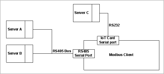
The following diagram summarizes the topology of a Modbus deployment over serial:

Setting up the Hardware
- Connect the development PC to the FX30S using a USB-to-serial cable. For a list of RS-232/RS-485 pin-outs, see: FX30S Serial Connector Pin-outs.
- Install Modbus simulation software onto the development PC and configure it to use the USB-to-serial cable with the following settings:
- Baud Rate: 9600
- Parity: None
- Data bits: 8
- Stop bits: 1
Note
You can optionally choose to use RS-485 instead of RS-232 on the FX30S only.
Setting up Modbus on the FX30S Through Octave
Follow the steps below to configure Octave to communicate with a Modbus server device:
- Select your FX30S in the Octave dashboard, and then navigate to Build > Device > Services.
- Locate the Modbus section, and click the sprocket icon to the right of UART1 to configure it.
Notes
- Ensure the device's UART is not already allocated to another Service, otherwise the UART cannot be configured.
- The FX30S may reboot the first time that a new bus is created, and will reboot when a the serial configuration is switched between RS-232 and RS-485.
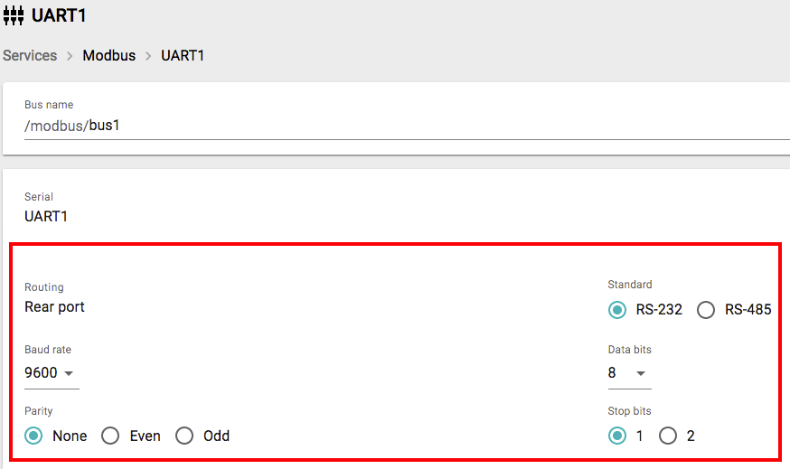
- Set Baud Rate to 9600, Standard to RS-232, Parity to None, Data bits to 8, and Stop bits to 1. This configures the client device. If you're using RS-485, set the Standard accordingly. Selecting RS-485 gives you the option to enable the Terminating resistor field. Do this only if required for your hardware.

- Configure a bus for the server device as described below in Configuring a Bus.
Setting up Modbus Communications via TCP
This section shows how to use a development PC as an asset that communicates with an FX30 using Modbus over TCP. In this configuration, the FX30 acts as the client device while the PC acts as a server device running Modbus simulation software to experiment with reading/writing values. The FX30 is connected to a TCP/IP network via its Ethernet connection.
Notes
- Your FX30 must be running firmware 2.0.4 or higher to use Modbus TCP connectivity in Octave.
- With versions before 3.1.0, you must enable the FX30 firewall rules to connect to the Modbus TCP assets on port 502 by running the following command once locally on the FX30 via ssh:
iptables -I INPUT -i eth0 -p tcp -m tcp --sport 502 -j ACCEPT
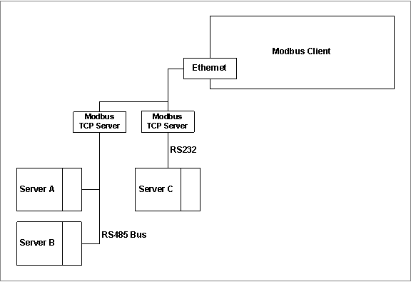
The following diagram summarizes the topology of a Modbus deployment over TCP:

Setting up the Hardware
Follow up the steps below to prepare the FX30 for Modbus TCP-based communications over Ethernet:
- Ensure that the FX30's firewall has been configured to allow a response on any interface for a device-initiated request. For more information on this configuration see the FX30 User Guide.
- Connect the FX30 to a TCP-based router on your network via Ethernet. The network must be the same one that the server device (asset) is connected to.
- Identify a free IP address on your network (e.g., 192.168.0.30) and the netmask that your network is using (e.g.,
255.255.255.0). These will be the IP address and netmask of the FX30 Modbus client. You will configure the FX30 with these parameters via Octave in a subsequent step below. - Verify that this IP address is not in a subnet already taken by the FX30 system:
- Connect to SSH.
- Run
ip a. - Check the different connectivity subnet ranges. The default value for an SSH connection is 192.168.2.2/24 and as a consequence, this subnet should not be used.
- Navigate to the Octave dashboard and ensure your FX30 device is selected.
- Navigate to Build > Device > Services, locate the Modbus section, and click eth0.
- Enter the IP address you identified in step 3 into the IP field.
- Enter the netmask you identified in step 3 into the Netmask field using CIDR notation. For example, a netmask of
255.255.255.0will be entered as24. - Click Save. The network configuration will be sent to the FX30.
- Verify that the FX30 has been assigned to the correct IP address using your router's dashboard.
- Configure a bus for the server device as described below in Configuring a Bus.
Configuring a Bus
After you have set up your FX30 or FX30S for Modbus communications, follow the steps below to configure a bus:
- (Optional) Enter a unique name for the bus in the Bus name field. If no name is given, a default will be used.
Note
The bus name and server name will be used to create a Resource in the Data Hub which is why the bus name must be unique. Server names however, can be re-used on other buses.
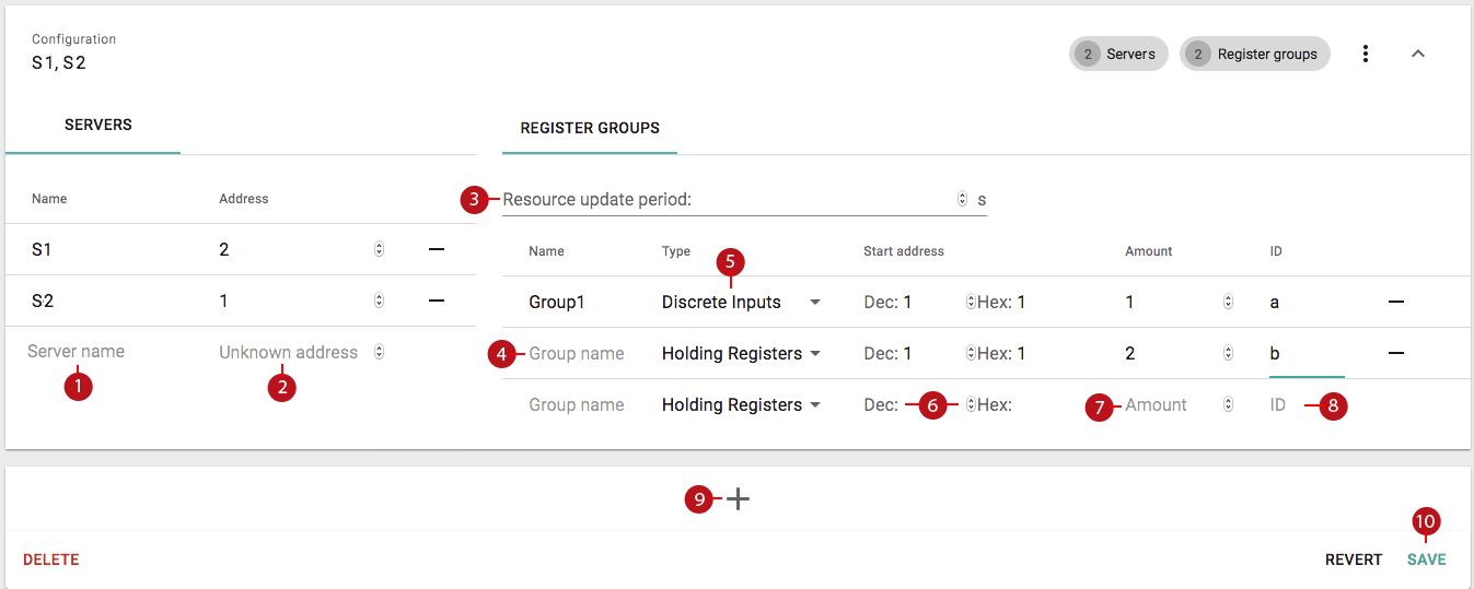
- Click in the Server name field (1) under Servers and enter the name of the first server device:

Note that the Configuration's name will automatically update to include a comma-separated list of the names entered.
- Click in the Unknown Address field (2) and enter the server's address.
Note
A server name can only be associated with one address. Bus and server names will be used to create Resources for each server.
- (Optional) Repeat the previous two steps to add additional servers with the same Modbus register configuration.
- Click in the Group name field (4) and enter the name of a group. A group defines the type of input along with the starting address and number of registers to allocate for the server.
Note
Register group names must be unique under a server, but can be re-used on other servers.
- Set the Type field (5) to the appropriate Modbus register type: Discrete Inputs, Coils, Input Registers, or Holding Registers.
- Set the address field (6) using either the Dec or Hex fields to define the first register in the group (using decimal or hexadecimal respectively), and set the Number field (7) to define the number of registers in the group. Together these define the starting address and length (number) of registers in the group.
- Click in the Default register update period field (3) under Register Groups and enter the amount of time to wait, in seconds, between accessing the registers.
Note
On devices with firmware version 3.x and higher, the period can be set individually for each register group, in addition to the global default period for all register groups.
- (Optional) Repeat steps 5 through 8 to add additional register groups to the server.
- (Optional) If you want to add other types of Modbus assets, or different Register configuration: click the "+" button (9) at the bottom to add a new Modbus Configuration. Each Modbus Configuration defines a set of server devices and groups.
- Click Save (10) at the bottom right-hand corner to save the Modbus Configuration(s).
Verifying Resources
Follow the steps below to identify and verify the Resources that have been created for your bus:
- Navigate to Build > Device > Resources in the Octave dashboard.
- Locate and expand modbus and verify that your bus name exists (e.g.
/modbus/bus1). - Verify that each of your servers exist under the bus name and expand them (e.g.
/modbus/bus1/server1). - Verify that a value Resource and a request Resource exist under each server (e.g.,
/modbus/bus1/server1/value,/modbus/bus1/server1/request). Note that the request Resource will be used to send requests to the server.
Reading Register Values
- Use the Modbus simulator on the development PC to change the values of the register(s) allocated to a Group.
- Use the following steps to view the value(s) of the register(s) in Octave:
- Navigate to Build > Device > Observations, create a new Observation that sends events to the Cloud Stream, and save it. Wait for Octave to poll the device and then view the Observation's Last Value field to see the raw data read from the server.
- Navigate to Build > Device > Streams > and locate events related to these changes in the register values. The Value field for a successful Modbus event should look similar to the following example:
"elems": {
    "modbus": {
      "bus1": {
        "server1": {
          "Group1": {
            "data": [
              0, 0, 0, 0, 0, 0, 0, 0
            ],
            "error": {
              "errno": 0
            }
          }
        }
      }
    }
  }
Sending Requests to the Server Device
There are currently two methods/uses for sending requests to a server device:
- Reading or Writing a Modbus Register via Octave
- Reading or Writing a Modbus Register via an Edge Action
Reading or Writing a Modbus Register via Octave
The request/send Resource (e.g., /modbus/bus1/server1/request/send) can be used to send requests to a server device (i.e., to read from and write to a Modbus register).
The following steps illustrate how to use a request to write to registers on the server device via Octave:
- Navigate to Build > Device > Resources.
- Locate and expand the request entry for your server (e.g., modbus > bus1 > server1 > request).
- Click the edit button to the right of the send property. This displays the JSON definition for the send request in a popup.
- Enter the JSON formatted request in the popup. Most fields are self-explanatory. There is an optional "id" field which will be passed unmodified into the JSON-formatted result after the request is processed.
For example, the following JSON will request Modbus to write the values 100 and 101 to holding registers 1 and 2 using a request ID named write_test:
{
  "id": "write_test",
  "request": "W",
  "type": "HLD",
  "address": 1,
  "data": [100, 101]
}
Note
See Modbus Configuration JSON Format for a description of these payload fields.
- Click Set. This sends the request to the server device.
- In the Modbus simulator software, verify that the register(s) were updated.
The result of the write operation will be written to the request/value Resource in JSON format. The format is similar to that of the polled register results under /modbus/<bus>/<server>/value. If provided, the optional "id" field will be copied to the result. This can be useful for differentiating between multiple requests. If an error occurred, the error number and description will be populated in the JSON.
{
  "id":"write_test",
  "data":[null],
  "error":{
    "errno":0
  }
}
The procedure to request a reading of registers is nearly identical to that for writing. Only the request and result JSON structures differ slightly: the request contains a number field for the number of registers to read. The result contains a data field on success. For example, to read 4 holding registers, starting at base 32:
{
  "id": "read_test",
  "request": "R",
  "type": "HLD",
  "address": 32,
  "number":4
}
The successful result will look like this:
{
  "id":"read_test",
  "data":[8,9,11,12],
  "error":{
    "errno":0
  }
}
Reading or Writing a Modbus Register via an Edge Action
A request can be programmatically sent in the return statement of an Edge Action. For example, to write to a register:
- Navigate to Build > Device > Action and click Add Edge Action.
- Configure the Observation.
- In the code window, add the following code:
function(event) {
   // Your code here
   return {
      "dh://modbus/bus1/server1/request/send": [{"id":"write_test","request":"W","type":"HLD","address":1,"data":[100,101]}]
   }
}
The JSON key returned refers to the request entry in the Datahub (dh entity) and sets the value to the request to send. In the example above, the JSON will write values 100 and 101 to holding registers 1 and 2 using a request named write_test.
- When the Edge Action occurs, use the Modbus simulator software to verify that the registers were updated on the server device.
- The result of the write operation can also be checked by reading the resulting JSON at
/modbus/bus1/server1/request/value.
Identifying Request Errors
Use any of the following methods to identify error responses from requests:
- Set up an Observation for the group, navigate to Device > Streams > groupname, and locate events related to the request. If an error occurred (e.g. a timeout occurred because the device could not be reached) the JSON will contain a non-zero errno and a description in errstr, similar to the following example:
"elems": {
    "modbus": {
      "bus1": {
        "server1": {
          "Group1": {
            "data": []
            "error": {
              "errno": -110,
              "errstr": "Connection timed out"
            }
          }
        }
      }
    }
  }
- Alternatively, navigate to Device > Resources, expand modbus > bus name > server name > value. Locate the group name and expand it. The error number and description are available under error.
Configuring and Verifying Modbus Directly From the Resource Tree
The underlying JSON that configures Modbus in the Datahub can be directly edited using the following steps:
- Navigate to Build > Device > Resources.
- Locate the modbus/config Resource.
- (Optional) Click the expansion icon to see the whole JSON structure.
- Click the edit icon to display the JSON editor.
- Modify the JSON as required and click Set. A reference guide for this JSON is provided here.
Updated over 2 years ago
