GPIO Guides
This topic describes how to configure a GPIO pin in Octave and verify that Octave can control/monitor it. This process is necessary to identify a device's pin in Octave as either input or output and whether it is analog or digital. Once complete, the configured pin is then available in Octave as a Resource through which you can enable it to emit output (voltage) or read input signals.
Identifying and Viewing GPIO Pinouts
Before configuring a GPIO pin in Octave, first identify the pin's number on your chosen device using appropriate the pin map:
You will use this pin number in the steps below to specify the pin designation in Octave when configuring an input or output pin.
GPIO Output
Configuring a GPIO Output
A GPIO output pin on an Octave edge device emits voltage (e.g., to control an asset). Setting up a GPIO output involves configuring a pin on the Octave edge device as an output pin which in turn, creates an Output (Actuator) Resource for the pin that will be available on the Build > Device > Resources screen. You can then enable and set the pin's value using that Resource.
Follow the steps below to configure a device's pin in Octave as a digital output pin:
- Navigate to Build > Device > Services, locate the GPIO section, and click Configure.
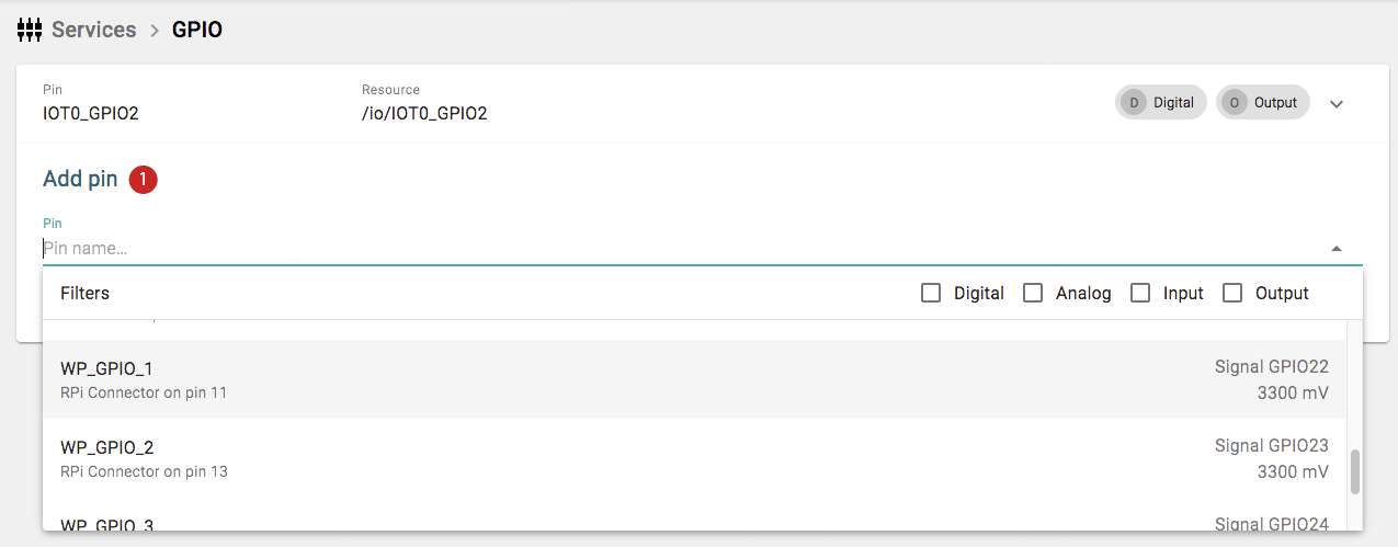
- Locate the Add pin section (1):

- Click the Pin drop down (2) and select a GPIO pin (e.g., WP_GPIO_2 for a mangOH Red output pin, EXT_IO3_DO for an FX30 rear port pin, IOT0_GPIO4 for an IoT expansion board pin, etc.). Note the expected voltage indicated for the pin which will be either 1800mV or 3300mV.
- (Optional) Change the name in Resource (3) to a more descriptive name.
- Set the Direction (4) to Output.
- Click Add (5). The configured output pin appears in the list of GPIO Services.
- Enable and set the pin's value in the Resource as described here.
Note
When adding a GPIO output, the output will take on the current state of the GPIO pin. If that GPIO output had been previously configured with a value set, then Octave will apply that previously configured value to the GPIO output. This ensures that pin values don't change state unexpectedly when a configuration is applied.
GPIO Input
A GPIO input pin on an Octave edge device receives are signals which are pushed by assets at some arbitrary time and interval. You will create an input in Octave any time you have an asset connected to the Octave edge device that you want to monitor in Octave.
Note
If the asset does not push data signals, then you may be able to monitor it using a Sensor Resource instead of an Input Resource.
Configuring a Digital Input
Setting up a GPIO input involves configuring a pin on the Octave edge device as an input pin which in turn, creates an Input Resource for the pin that will be available on the Build > Device > Resources screen. You can then enable the pin using that Resource.
Note
You can set up a pin for either digital input (as described below) or analog input
Follow the steps below to configure a device's pin in Octave as a digital input pin:
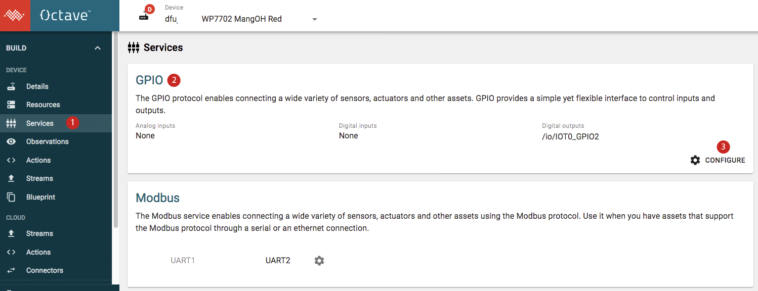
- Navigate to Build > Device > Services (1), locate the GPIO section (2), and click Configure (3):

- Locate the Add pin section (1):

- Click the Pin drop down and select a GPIO pin (e.g., WP_GPIO_1 for a mangOH Red input pin, EXT_IO2_DI for an FX30 rear port pin, IOT0_GPIO1 for an IoT expansion board pin, etc.).
- Note the expected voltage indicated for the pin which will be 1800mV.
- (Optional) Change the name in Resource (2) to a more descriptive name. By default, the Resource created by the IO service will share the name of the pin that it connects. However, it's usually much more practical to use a short name that describes what you are actually connecting. For example, red_led might make sense for a digital output connected to an LED.

- Ensure the Direction is set to Input (I).
- Set Pull to Up.
- Click Add (3). The configured pin appears in the list of GPIO Services.
Configuring an Analog Input
Follow the steps below to configure a device's pin in Octave as an analog input pin:
- Navigate to Build > Device > Services, locate the GPIO section, and click Configure.
- Locate the Add pin section.
- Click the Pin drop down and select a GPIO pin (e.g., ADC0).
- Note the expected voltage range indicated for the pin under the Voltage label.
- (Optional) Change the name in Resource to a more descriptive name. By default, the Resource created by the IO service will share the name of the pin that it connects. However, it's usually much more practical to use a short name that describes what you are actually connecting. For example, photoresistor might make sense for an analog input name.
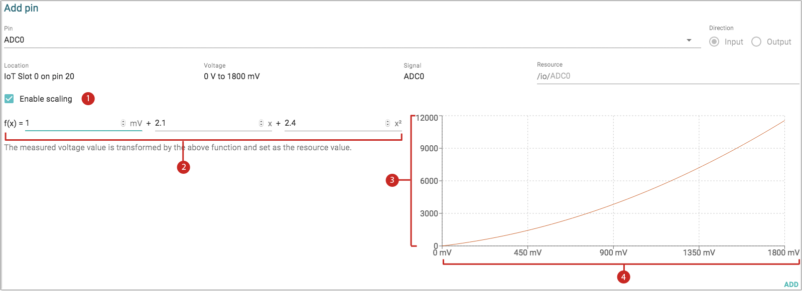
- (Optional) Click Enable Scaling (1) to customize the voltage curve and modify the function parameters (2) to adjust the graph. This feature transforms the voltages reported by Octave (shown on the Y-axis (3)) from the actual voltages measured on the pin (shown on the X-axis (4)) over the pin's voltage range:

Note
Due to a bug in Octave, scaling on the ADC may not be taken into account. To rectify this you can multiply the following scaling coefficient to the first addend of the function:
a1 = 1000mv / 1700mV ~= 0.58For example, in the screenshot above you would multiply 1 * 0.58 to get 0.58. The function would then be:
f(x) = 0.58 + 2.1 + 2.4Note that you may need to tweak the value for your specific hardware.
- Click Add. The configured pin appears in the list of GPIO Services.
- Enable and verify the pin Resource as described here Input Resources.
GPIO Input Tutorials
The following tutorials show how to work GPIO inputs using an IoT Expansion Breadboard.
- Tutorial 1: Driving the Value by Jumping the PIN to Ground
- Tutorial 2: Detecting Changes from a Photocell
For these tutorials you'll need to:
- Take a look at the IoT Expansion Board pin map and locate the ADC pin (Pin 20).
- Wire up the ADC pin.
- Configure an output pin via the GPIO service.
Tutorial 1: Driving the Value by Jumping the PIN to Ground
In this tutorial, you will use a jumper wire to bridge the ADC pin (Pin 20) on the IoT Expansion Board to a ground pin, and then view the change in value of the ADC pin using Octave.
Note
For this tutorial you will need a jumper wire.
Preparing the Pin in Octave
Follow the steps below to set up and configure an ADC pin on the device via Octave:
- Add an analog input pin for GPIO pin for ADC0.
- Add an Observation for the pin's resource (/io/ADC0/value ).
- Enable the pin's Resource and set its period to a short time period (e.g., 5 seconds).
Viewing the Change in Value of the ADC Pin.
Follow the steps below to view and modify the value of the ADC pin:
- Navigate to Build > Device > Streams.
- Locate your device in the Stream list and ensure it is expanded.
- Locate the adc_0 stream and click on it.
- Note the pin's maximum value, which should be appearing in the list of events at the interval specified via the period property that you configured in the previous section.
- Review the IoT Expansion Board pin map and identify the location of the ADC pin (Pin 20) and a ground pin (e.g., Pin 21).
- Bridge the ADC pin (Pin 20) to a ground pin (e.g., Pin 21) using a jumper wire.
- Wait for the configured interval to elapse. The next event in the stream should indicate a value below the pin's expected range (i.e., a value below 100mV such as 17mV).
Tutorial 2: Detecting Changes from a Photocell
In this tutorial, you will wire up a photocell to the ADC pin (Pin 20) on the IoT Expansion Board and then view the variations in voltage that occur as the amount of light detected changes.
Note
For this tutorial you will need the following electronic components:
- mangOH Red with the IoT Expansion Board installed
- photocell
- 1 kilo Ohm resistor
- three jumper wires
- (optional) a breadboard to make the connections on
Wiring the Circuit
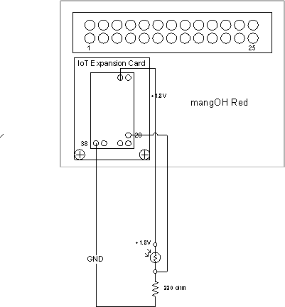
- Wire up the following circuit:


- Power on the mangOH Red.
Preparing the Pin in Octave
- Add an analog input pin for GPIO pin for ADC0.
- Add an Observation for the pin's resource (/io/ADC0/value).
- Enable the pin's Resource and set its period to a short time period (e.g., 5 seconds).
Viewing the Change in Value of the ADC Pin
Follow the steps below to view and modify the incoming value on the ADC pin:
- Navigate to Build > Device > Streams.
- Locate your device in the Stream list and ensure it is expanded.
- Locate the adc_0 stream and click on it.
- Note the pin's current value, which should be appearing in the list of events at the interval specified via the period property that you configured in the previous section.
- Place your finger over the photocell to reduce the light level.
- Wait for the configured interval to elapse. The next event in the Stream should indicate a significantly lower value corresponding to the change in light.
Setting the FX30 LED Colors via GPIO
You can set the color of the FX30/FX30S's power and user LEDs by assigning different combinations of values to the LED_PWR_... and LED_USR_... GPIO pins.
Setting the Color of the Power LED
Follow the steps below to set the color of the FX30/FX30S's power LED:
- Open the Octave Dashboard.
- Add GPIO outputs for LED_PWR_GRN_FCN, LED_PWR_GRN, and LED_PWR_RED.
- Navigate to the Resources screen and expand the io node.
- Set the values for the three GPIO outputs created in Step 2 according to the following table and click Apply. The power LED should change color accordingly.
| Color | LED_PWR_GRN_FCN | LED_PWR_GRN | LED_PWR_RED |
|---|---|---|---|
| None (off) | true | true | false |
| Red | true | true | true |
| Amber | true | false | true |
| Green | true | false | false |
Setting the Color of the User LED
Follow the steps below to set the color of the FX30/FX30S's user LED:
- Open the Octave Dashboard.
- Add GPIO outputs for LED_USR_GRN and LED_USR_RED.
- Navigate to the Resources screen and expand the io node.
- Set the values for the two GPIO outputs created in Step 2 according to the following table and click Apply. The power LED should change color accordingly.
| Color | LED_USR_GRN | LED_USR_RED |
|---|---|---|
| None (off) | true | true |
| Red | true | false |
| Amber | false | false |
| Green | false | true |
Updated over 3 years ago
