Physically Connecting Digital Output to an IoT Expansion Breadboard
Now that you've decided to connect an analog signal to your IoT Expansion Breadboard, you'll need to:
- Take a look at the IoT Expansion Board pin map and locate the ADC pin (Pin 20).
- Wire up the ADC pin.
- Configure the pin via the GPIO service.
You can then perform the steps in the following tutorials to verify that the pin is working correctly as an analog input:
- Tutorial 1: Driving the Value by Jumping the PIN to Ground
- Tutorial 2: Detecting Changes from a Photocell
Tutorial 1: Driving the Value by Jumping the PIN to Ground
In this tutorial, you will use a jumper wire to bridge the ADC pin (Pin 20) on the IoT Expansion Board to a ground pin, and then view the change in value of the ADC pin using Octave.
Note: For this tutorial you will need a jumper wire.
Adding the Analog Input
Follow the steps below to configure the analog input pin:
- Navigate to Device > Services, locate the GPIO section, and click Configure.
- Locate the Add pin section.
- Click the Pin drop down and select ADC0.
- Note the expected voltage range indicated for the pin which will be 100mV to 1700mv.
- (Optional) Change the name in Resource to a more descriptive name.
- Click Add. The configured pin appears in the list of GPIO Services.
Adding an Observation
Follow the steps below to create an Observation that monitors the value of the configured analog pin:
- Navigate to Device > Observations.
- Click Add Observation.
- Click the Observed resource drop down and select /io/ADC0/value.
- Enter an Observation name.
- Ensure Send events to is set to Cloud Stream.
- Click Save.
Configuring the Resource
Follow the steps below to configure the ADC0 resource.
- Navigate to Device > Resources.
- Locate and expand the io/ADC0 resource.
- Click the drop down for the enable property and set it to true.
- Click the drop down for the period property, set it to a short time period (e.g., 5 seconds) and click Set.
- Click Apply.
Viewing the Change in Value of the ADC Pin.
Follow the steps below to view and modify the value of the ADC pin:
- Navigate to Device > Streams.
- Locate your device in the stream list and ensure it is expanded.
- Locate the adc_0 stream and click on it.
- Note the pin's maximum value, which should be appearing in the list of events at the interval specified via the period property that you configured in the previous section.
- Review the IoT Expansion Board pin map and identify the location of the ADC pin (Pin 20) and a ground pin (e.g., Pin 21).
- Bridge the ADC pin (Pin 20) to a ground pin (e.g., Pin 21) using a jumper wire.
- Wait for the configured interval to elapse. The next event in the stream should indicate a value below the pin's expected range (i.e., a value below 100mV such as 17mV).
Tutorial 2: Detecting Changes from a Photocell
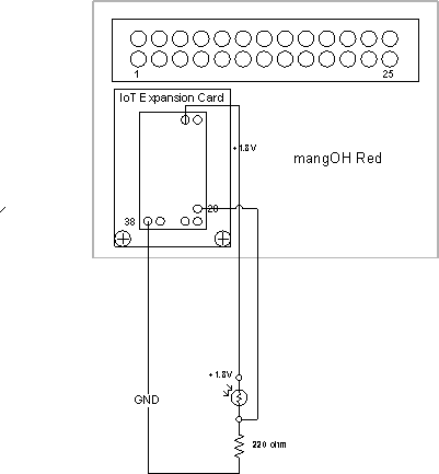
In this tutorial, you will wire up a photocell to the ADC pin (Pin 20) on the IoT Expansion Board and then view the variations in voltage that occur as the amount of light detected changes.
Note: For this tutorial you will need the following electronic components:
- mangOH Red with the IoT Expansion Board installed
- photocell
- 1 kilohm resister
- three jumper wires
- (optional) a breadboard to make the connections on
Wiring the Circuit
- Wire up the following circuit:


- Power on the mangOH Red.
Adding the Analog Input
Follow the steps below to configure the analog input pin:
- Navigate to Device > Services, locate the GPIO section, and click Configure.
- Locate the Add pin section.
- Click the Pin drop down and select ADC0.
- (Optional) Change the name in Resource to a more descriptive name.
- Click Add. The configured pin appears in the list of GPIO Services.
Adding an Observation
Follow the steps below to create an Observation that monitors the value of the configured analog pin:
- Navigate to Device > Observations.
- Click Add Observation.
- Click the Observed resource drop down and select /io/ADC0/value.
- Enter an Observation name.
- Ensure Send events to is set to Cloud Stream.
- Click Save.
Configuring the Resource
Follow the steps below to configure the ADC0 resource.
- Navigate to Device > Resources.
- Locate and expand the io/ADC0 resource.
- Click the drop down for the enable property and set it to true.
- Click the drop down for the period property, set it to a short time period (e.g., 5 seconds) and click Set.
- Click Apply.
Viewing the Change in Value of the ADC Pin.
Follow the steps below to view and modify the incoming value on the ADC pin:
- Navigate to Device > Streams.
- Locate your device in the stream list and ensure it is expanded.
- Locate the adc_0 stream and click on it.
- Note the pin's current value, which should be appearing in the list of events at the interval specified via the period property that you configured in the previous section.
- Place your finger over the photocell to reduce the light level.
- Wait for the configured interval to elapse. The next event in the stream should indicate a significantly lower value corresponding to the change in light.
Updated about 5 years ago
